Ignition Coil Wiring Diagram - Ignition System Wiring Diagram 2004 2006 2 2l Chevrolet Malibu. This simple system is easy for even the novice mechanic to wire. The construction of the battery, ignition switch. Primary current is an available test on all types: The coil primary winding contains 100 to 150 turns of heavy copper wire. It shows the components of the circuit as simplified shapes, and the capacity and signal friends between the devices.
1 trick that we use is to print the same wiring picture off twice. Ignition coil ballast resistor wiring diagram. Accuspark wiring diagrams ignition system basics matt dubanoski 1929 a 6v to 12v diagram help basic full 12 volt alternator conversion farmall cub converting one wire systems short course relay an electrical circuit 5 4 8 primary how motorcycle for ford 9n 2n 8n your boat madcomics distributor you understand read car 3 typical. The job of the ballast resistor was to inhibit current to a level that would not overheat the coil. This simple system is easy for even the novice mechanic to wire.
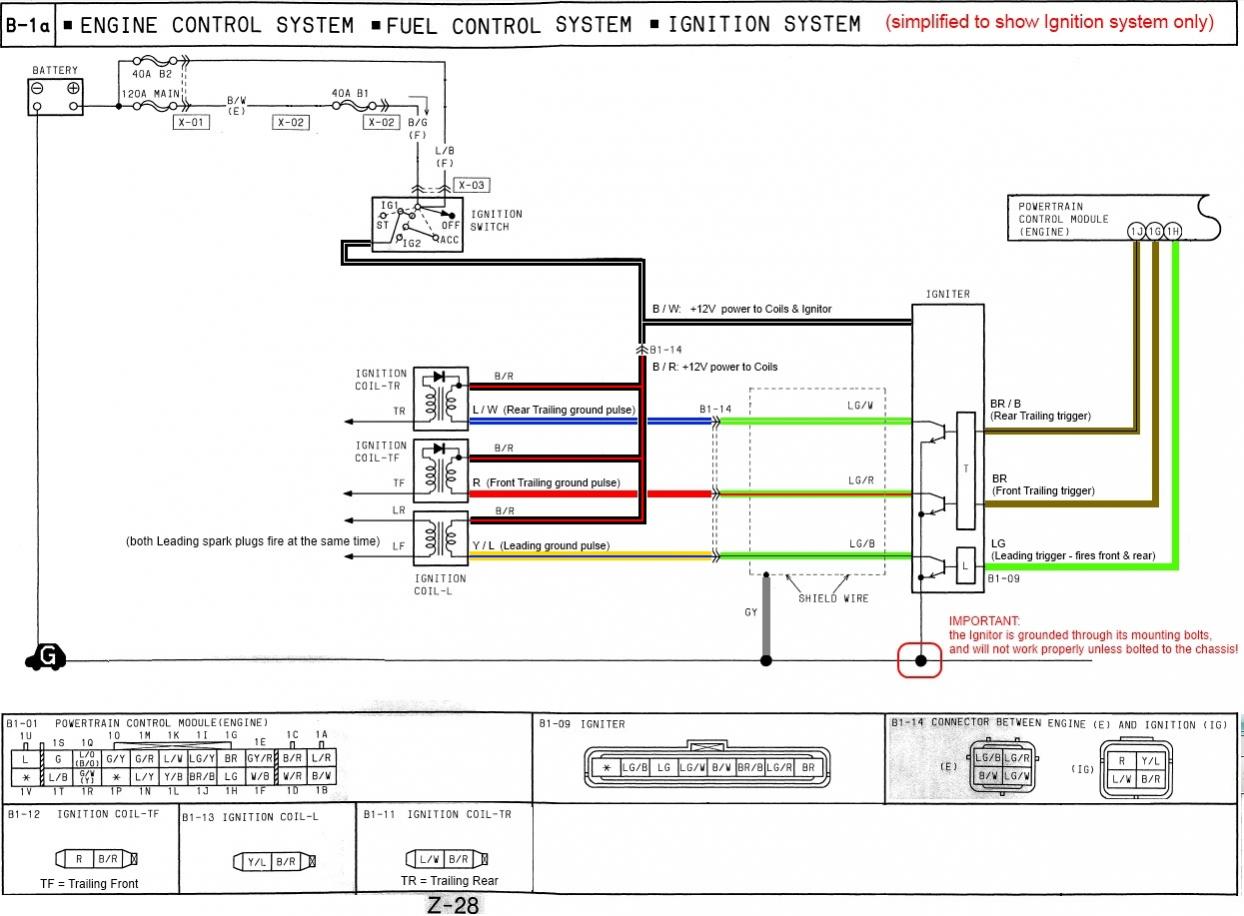
How The Fd S Ignition System Works Simplified Wiring Diagram Rx7club Com Mazda Rx7 Forum from www.rx7club.com This is the only wire that makes electrical contact with the negative coil terminal. The purpose of the ignition system is to create a spark that will ignite the fuel air mixture in the cylinder of an engine. A wiring diagram is a streamlined standard photographic representation of an electric circuit. This simple system is easy for even the novice mechanic to wire. Ignition coil, distributor, and spark plug is similar to previous. 3 terminal ignition switch wiring diagram number diagrams evening. Ignition coil ballast resistor wiring diagram welcome to my internet site this blog post will certainly discuss concerning ignition coil ballast resistor wiring diagram. Ignition system ignition coil motorcycle wiring scrambler motorcycle motorcycles honda civic engine remote car starter trailer wiring diagram boat wiring.
Ignition coil ballast resistor wiring diagram welcome to my internet site this blog post will certainly discuss concerning ignition coil ballast resistor wiring diagram.
Each part ought to be set and connected with different parts in specific manner. There are three circuits that can be used to trigger the msd ignition; It shows the elements of the circuit as streamlined shapes, as well as the power and also signal links in between the tools. The coil primary winding contains 100 to 150 turns of heavy copper wire. This applies to all old cub cadet ford jacobsen john deere wheel horse case and. The spark plug wire, the power wire and the ignition switch wire. Ignition coil ballast resistor wiring diagram. The spark is also much more intense, which increases power and mileage. Ignition system ignition coil motorcycle wiring scrambler motorcycle motorcycles honda civic engine remote car starter trailer wiring diagram boat wiring. It is typically just a wire wound transformer filled with an insulator. It contains both primary and secondary winding circuits. The purpose of the ignition system is to create a spark that will ignite the fuel air mixture in the cylinder of an engine. This tutorial will help you test the ignition coil, ignition module, and the crankshaft position sensor:
March 12, 2019 by larry a. Cruze has 4 independent ignition coil on plug system, built in one single body, with 4 power modules inside them. The typical automotive ignition system prior to 1974 consisted of a coil and ballast resistor, with breaker points to interrupt the current flow when a spark was needed. A coil upgrade is also necessary. The purpose of the ignition system is to create a spark that will ignite the fuel air mixture in the cylinder of an engine.
Ignition Wiring Diagramm Pvl Ignitions from pvl-zuendungen.de A schematic diagram of an electronic ignition system is shown in figure 2.36. A coil upgrade is also necessary. Each part ought to be set and connected with different parts in specific manner. It shows the parts of the circuit as streamlined forms, and the power as well as signal links in between the tools. This wire must be insulated so that the voltage does not jump from loop to loop, shorting it out. Basic ignition system wiring diagram. Otherwise, the structure won't function as it ought to be. The spark plug wire, the power wire and the ignition switch wire.
The purpose of the ignition system is to create a spark that will ignite the fuel air mixture in the cylinder of an engine.
A wiring diagram is a streamlined standard photographic representation of an electrical circuit. The aftermarket cdi module must be placed between ecu signal and coil, jumping the stock power modules. This wire must be insulated so that the voltage does not jump from loop to loop, shorting it out. Ignition solutions for older small engines and garden pulling tractors. Wire diagram for most b s engines. This applies to all old cub cadet ford jacobsen john deere wheel horse case and. Cruze has 4 independent ignition coil on plug system, built in one single body, with 4 power modules inside them. The purpose of the ignition system is to create a spark that will ignite the fuel air mixture in the cylinder of an engine. Because the output spark is very much higher voltage (20,000v) than the car battery (12v), it doesn't care if the battery polarity is helping or hindering by a meager 12 to 14 volts in battery potential. March 12, 2019 by larry a. The job of the ballast resistor was to inhibit current to a level that would not overheat the coil. The coil primary winding contains 100 to 150 turns of heavy copper wire. A coil upgrade is also necessary.
It shows the components of the circuit as simplified shapes, and the capacity and signal friends between the devices. Basic ignition system wiring diagram. It shows the elements of the circuit as streamlined shapes, as well as the power and also signal links in between the tools. A schematic diagram of an electronic ignition system is shown in figure 2.36. This wire must be insulated so that the voltage does not jump from loop to loop, shorting it out.
How To Wire Ignition Coil Ford Muscle Cars Tech Forum from i.imgur.com Because the output spark is very much higher voltage (20,000v) than the car battery (12v), it doesn't care if the battery polarity is helping or hindering by a meager 12 to 14 volts in battery potential. March 12, 2019 by larry a. The typical automotive ignition system prior to 1974 consisted of a coil and ballast resistor, with breaker points to interrupt the current flow when a spark was needed. Cylinder to cylinder variations are valuable. Is this same as the scion tc? Ignition coil, distributor, and spark plug is similar to previous. A wiring diagram is a streamlined standard photographic representation of an electric circuit. It shows the parts of the circuit as streamlined forms, and the power as well as signal links in between the tools.
It shows the elements of the circuit as streamlined shapes, as well as the power and also signal links in between the tools.
Ford ignition coil wiring diagram wiring diagram is a simplified enjoyable pictorial representation of an electrical circuitit shows the components of the circuit as simplified shapes and the gift and signal friends amid the devices. Wiring diagram for ignition coil. The wired differences matt dixon southern illinois university carbondale,. Otherwise, the structure won't function as it ought to be. Basic ignition system wiring diagram. Briggs engine 125k02 0137 ignition system. 2,3 and 4 wire coil versions are different in control & monitoring strategies. Is this same as the scion tc? Accuspark wiring diagrams ignition system basics matt dubanoski 1929 a 6v to 12v diagram help basic full 12 volt alternator conversion farmall cub converting one wire systems short course relay an electrical circuit 5 4 8 primary how motorcycle for ford 9n 2n 8n your boat madcomics distributor you understand read car 3 typical. These coils had very simple wiring. However, this diagram is a simplified variant of this arrangement. The construction of the battery, ignition switch. The coil primary winding contains 100 to 150 turns of heavy copper wire.
Share :
Post a Comment
for "Ignition Coil Wiring Diagram - Ignition System Wiring Diagram 2004 2006 2 2l Chevrolet Malibu"


Post a Comment for "Ignition Coil Wiring Diagram - Ignition System Wiring Diagram 2004 2006 2 2l Chevrolet Malibu"